There are many applications for which a timer is very useful to turn a device on or off automatically after a preset interval - for example, switching off an irrigation system after 30 minutes of use, turning off a battery charger to prevent overcharging, etc.
Timing short intervals of milliseconds to minutes can easily be achieved using a NE555 chip. Unfortunately, this device is not suitable for timing longer intervals, and so a suitable alternative is required.
Binary Counting with the 4060B
 CMOS IC" width="79" height="57">
 The 4060B (pictured above) is a CMOS binary counter. Using a resistor and a capacitor, the counting speed can be set by the user very easily. The pins of the 4060B integrated circuit output the running count in binary as shown below:
0 = 0000000000
1 = 0000000001
2 = 0000000010
3 = 0000000011
4 = 0000000100
5 = 0000000101
6 = 0000000110
7 = 0000000111
8 = 0000001000
1 = 0000000001
2 = 0000000010
3 = 0000000011
4 = 0000000100
5 = 0000000101
6 = 0000000110
7 = 0000000111
8 = 0000001000
Each of the binary 1's and 0's is called a bit (much as the numbers 0,1,2...8,9 are called digits in the decimal number system). The furthest right bit represents 1, the next to the left represents 2, the next represents 4, the next 8, the next 16 and so on doubling every time you move one position to the left. Therefore 000010000 is binary for 16, and 000100000 is binary for 32.
To keep things simple, let's assume the count is increased by one every second. The rightmost bit (the 1's bit) will be off for one second, on for one second, off for one second and so on...
0000000001, 0000000010, 0000000011
The fifth bit from the right (the 16's bit) is therefore off for 16 seconds (when the count is 0-15), then on for 16 seconds (when the count is 16-31), then off for 16 seconds (when the count is 32-47), and so on.
With this knowledge, we can make a very accurate timer utilising our 4060B binary counter chip. Let's say we want a 16 second timer: we start the 4060B counter from 0, and wait until the 16's bit goes from 0 to 1. At that exact time we know that 16 seconds have elapsed. Similarly if we start the counter again, and wait until the 32's bit goes from 0 to 1, we know that 32 seconds have elapsed.
A timer which can only time, 1, 2, 4, 8, 16, 32, 64, 128, and so on seconds would not be very useful, but since we can adjust the speed of the count, any time interval from seconds to 24+ hours can be accurately timed.
4060B Timer
A schematic of the 4060B chip is provided below:
The pins labelled in red Q4-Q14 are the binary outputs: Q4 for the 16's, Q5 for the 32's, Q6 for the 64's and so on up to Q13 for the 8192's, and Q14 for the 16384's.
Just three external components are required to control the 4060B counter - two resistors and one capacitor. The frequency of the internal oscillator (i.e. the speed of the count) is set according to the equation given at the bottom of the schematic below:
Since Q14 represents the 16,384's and Q4 represents the 16's - we know it will take 1,024 times longer (16,384 / 16) for Q14 to flip from 0 to 1 than it takes Q4. So, for an example 2-hour timer (=7,200 seconds), we just need to fine-tune the circuit so that Q4 turns on after 7,200 / 1,024 seconds = 7.03 seconds, knowing that if that is done correctly, after exactly 2 hours Q14 will flip from 0 to 1.
Putting Together the Timer Circuit
 CMOS IC" width="597" height="435">
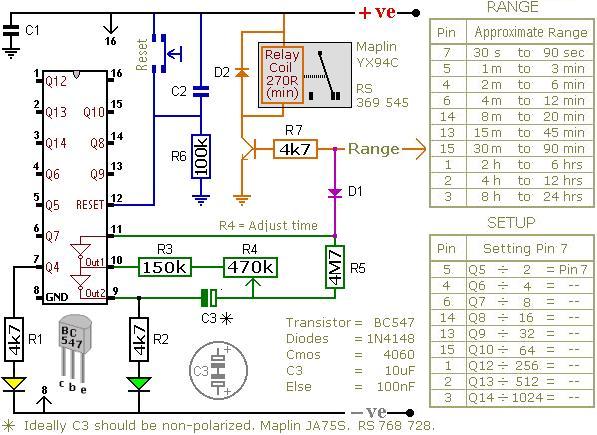
 The circuit shown above is a timer which energises a relay after a preset time has elapsed. It can be set to time an interval from 30 seconds to 24 hours.
The orange arrow labelled Range should be connected to a pin on the 4060B chip selected from the RANGE table. If for example, you require a timer to time 3 hours, connect it to pin number 1 on the chip since that pin corresponds to the time range 2hrs to 4hrs.
3 hours is 10,800 seconds, and we are using the output from pin 1 to trigger the relay. Looking at the SETUP table entry for pin 1 we see that we divide our target time (10,800 seconds) by 256 to obtain the on/off time for the yellow LED at pin 7 = 42.28 seconds. Therefore, if we adjust the potentiometer R4 so that the yellow LED turns on after approximately 42 seconds, we'll know that the relay will be energised after approximately 3 hours.
The diode D1 makes this a one-shot timer. This means that after the programmed time delay of 3 hours, the relay will stay on until the circuit is reset. If the diode is omitted from the circuit then you get a repeating timer with the relay off for 3 hours, on for 3 hours, off for 3 hours, and so on until the circuit it reset.
Repeat Timer Circuit
(just use NE555 to solve the short period problem)
Make a repeat timer circuit with large intervals between ON times
In our article Build Timer Circuits Using a 4060B we looked at how the 4060B binary counter can be used to make a timer. Such a timer can be used to time intervals lasting from seconds to 24+ hours, but when used as a repeat timer (i.e. toggling between ON and OFF indefinitely) the ON time is equal to the OFF time - for example, 10 minutes ON, 10 minutes OFF, 10 minutes ON etc.It is more common for a timer to be required to have different ON and OFF times - for example, 1 hour OFF, 1 minute ON, 1 hour OFF, 1 minute ON, etc. For time intervals of up to 5-10 minutes, a NE555 timer chip can achieve this with the different ON/OFF times set using a resistors and capacitors. However, for longer time intervals, the 555 is not reliable.
Using a 4060B with a 555 Timer
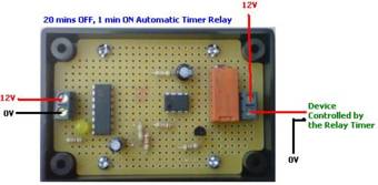
One of the easiest ways of putting together a reliable timer with long OFF intervals and short ON intervals is to use a 4060B together with a 555 timer. The 4060B accurately times the long OFF interval (up to 24 hours), and the 555 the short ON interval (up to 5 minutes).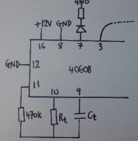
Pictured above is the 4060B part of the circuit which determines the duration of the OFF time interval. The values of the capacitor Ct and the resistor Rt fix the frequency (and therefore the speed) of the timer according to the formula:
Frequency = 1 / (2.3 x Rt x Ct)
Increasing the values of Rt or Ct* will slow down the timer; reducing them will speed up the timer.
* Ct should be a non-polarised capacitor.
The LED connected to pin 7 of the chip is used to estimate the freqency of the output from pin 3. If the LED goes through one complete ON/OFF cycle every 2 seconds (flashing ON for 1 second then OFF for 1 second etc), then it will take 1,024 times those 2 seconds for the output of pin 3 to go though one complete cycle = 2,048 seconds (34 minutes).
In our experimentation we found that a 10uF non-polarised capactor and a 6K8 resistor gave us a 40 minute pin 3 cycle time - i.e. ON for around 20 minutes, OFF for around 20 minutes and so on.
The 555 timer part of the circuit (pictured below) is used to time the short ON interval.
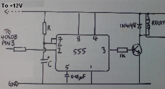
In this configuration, the output from pin 3 of the 555 chip is high (therefore energising the relay) when power is applied to the circuit from pin 3 of the 4060B. The relay will remain energised for a time period* set with the resistor R and capacitor C before turning off and staying off.
* In our experimentation we used R=470K and C=100uF to obtain a 1 minute timer.
How Does this Timer Circuit Work
Let's say we need a timer which will cycle OFF for 59 minutes and then ON for 1 minute indefinitely perhaps for an hourly monitoring application. First of all we set up the 4060B so that the time taken for the LED at pin 7 to go through one complete ON/OFF cycle is 1/1024 of 60 minutes = 3.52 seconds. (It is best to measure the time taken for 20+ cycles and then use a calculator to work out the time for one cycle accurately). Set up the 555 timer circuit for one minute changing the value of the resistor (using a variable resistor makes this easier).When the output of pin 3 of the 4060B goes high, the 555 circuit receives power. The relay will be energised as long as pin 3 of the 555 chip is high - a time we set as one minute in this example. After that one minute pin 3 of the 555 will go low and stay low. The 555 circuit will continue to receive power from the 4060B for 60/2 minutes = 30 minutes, but the relay will stay de-energised after the first minute. Then, after 30 minutes, pin 3 of the 4060B will go low again for 30 minutes removing power from the 555 circuit altogether which resets it. The cycle then repeats itself.
In short, the relay will be energised for one minute every time pin 3 of the 4060B goes high - an event which happens once every 60 minutes.
Bespoke Timer Circuit
Making Very Accurate Timers
Find out about how to make very accurate electronic timers
We have previously published many articles about electronic timers - ranging from short interval timers using the common 555 IC, long interval (multi-hour) timers using a 4060B binary counter IC, and repeat timer circuits which use both. We have also looked at commercial 12V programmable timer switches, and how battery powered programmable thermostats can be modified to operate as (more affordable) equivalents.
In this article we will look into how an accurate timer can be put together which will keep good time for weeks or months at a time.
The Importance of Timer Accuracy
Timers built around the 555 IC are only accurate up to a few minutes - after about 20 minutes that they can become wildly inaccurate. Similarly, 4060B-based timers can lose or gain many minutes per day.For many applications a far greater level of accuracy is required - for example, any timer which must turn a device on or off at exactly the same time every day for a fixed interval must be pretty accurate or the turn-on/off time will drift from day to day until it is completely wrong.
How do Clocks Keep Time
Even the cheapest watch or clock can keep time accurately to within a few seconds per 24 hours, so we should look at how they work. Within an electronic clock is a tiny quartz crystal which vibrates (resonates) in much the same way as a tuning fork - but at an incredible 32,768 times per second.
This frequency (32,768 Hertz) is chosen because it is equal to exactly 2x2x2...x2 (2^15) - and therefore it is easy to electronically divide the count by two 15 times to obtain a 1Hz signal (once per second) to trigger rotation of the seconds hand on the clock.
Making an Accurate Electronic Timer
Any electronic clock needs at least two main components - a quartz crystal and a counter. The counter simply counts the number of times the crystal has vibrated, and every time it reaches 32,768 it outputs a signal (indicating that one second has passed) and starts counting again from zero.Since we have used the 4060B binary counter chip in previous experiments, we will use it again here. Unfortunately this counter (though easy to find, reliable, and cheap) can only count up to 2^14 (16,384), and so it will give a signal twice per second (2Hz) instead of once - not a major problem, but something to remember.
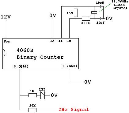
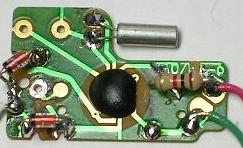
Above is shown a typical clock crystal 2Hz timebase circuit. This simple circuit emits a precise 2Hz signal which can then be used to keep accurate time. An LED is used to flash on and off - on for 0.25s, off for 0.25s and so on - to show that the circuit is working as it should.
Now we have a precision timebase, the rest of the timer can be put together simply - either using another binary counter to count the passing half seconds, or more likely, a small microprocessor (e.g. PIC) which will keep track of the passing seconds, minutes, hours, and days, and turn devices/components on and off as programmed by the user. Alternatively, the 2Hz signal can be used to trigger a small stepper motor to turn the seconds hand of a mechanical clock.
Precision One Second Timebase from a Quartz Clock
4 comments:
Excellent
I.m very much interested to build this circuit. As i.m a beginner please let me know whom to contact throughout the build so my project would be a success.
very good. I was wondering if i could program the astable to operate once per day for about 30 minutes. I am a beginner not very familiar with these
Just an observation: the 555 circuit above works as "one time shot". If you want it to repeat accordind the 4060 cicle,you have to connect the pin 4 (reset) to pin 2 (trigger) of 555 chip. Tested!
Post a Comment